


WEB Catalog


|
For Input/Output
∗The applicable protocols differ depending on the series. For details, refer to the catalog of each series. |


|
| Other Data |
|---|
| Series | Flow characteristics 4/2→3/5(A/B→E) C[dm3/(s・bar)] |
Flow characteristics 4/2→3/5(A/B→E) b |
Applicable cylinder size |
|---|---|---|---|
| EX600 | IP67 | PROFIBUS DP DeviceNet™ CC-Link EtherNet/IP™ EtherCAT PROFINET MRP (PROFINET) Ethernet POWERLINK Modbus TCP CC-Link IE Field EtherNet/IP™ IO-Link master unit |
SY3000,5000,7000 (Plug-in) SV1000,2000,3000 VQC1000,2000,4000 S0700(IP40) |
| Series | Download |
|---|---|
| EX600 |
|


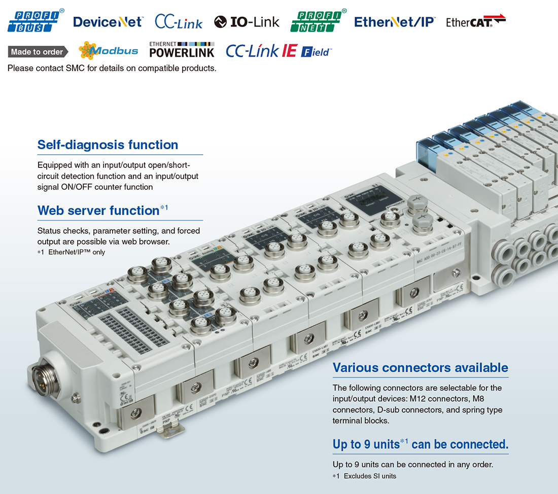
●Compatible Protocols
IO-Link is a communication technology for sensors and actuators that is an international standard, IEC61131-9.
This technology is used to send/receive device information such as manufacturer, product part number, parameters, and diagnostic data, as well as the control data including ON/OFF signals and measured values of the sensor, by connecting the IO-Link master and sensor in a 1:1 configuration.
IO-Link enables condition monitoring and error detection of the sensor and equipment, and it can contribute to the reduction of startup labor and recovery time and the realization of preventive and predictive maintenance.
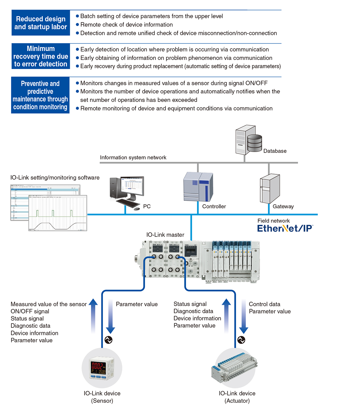
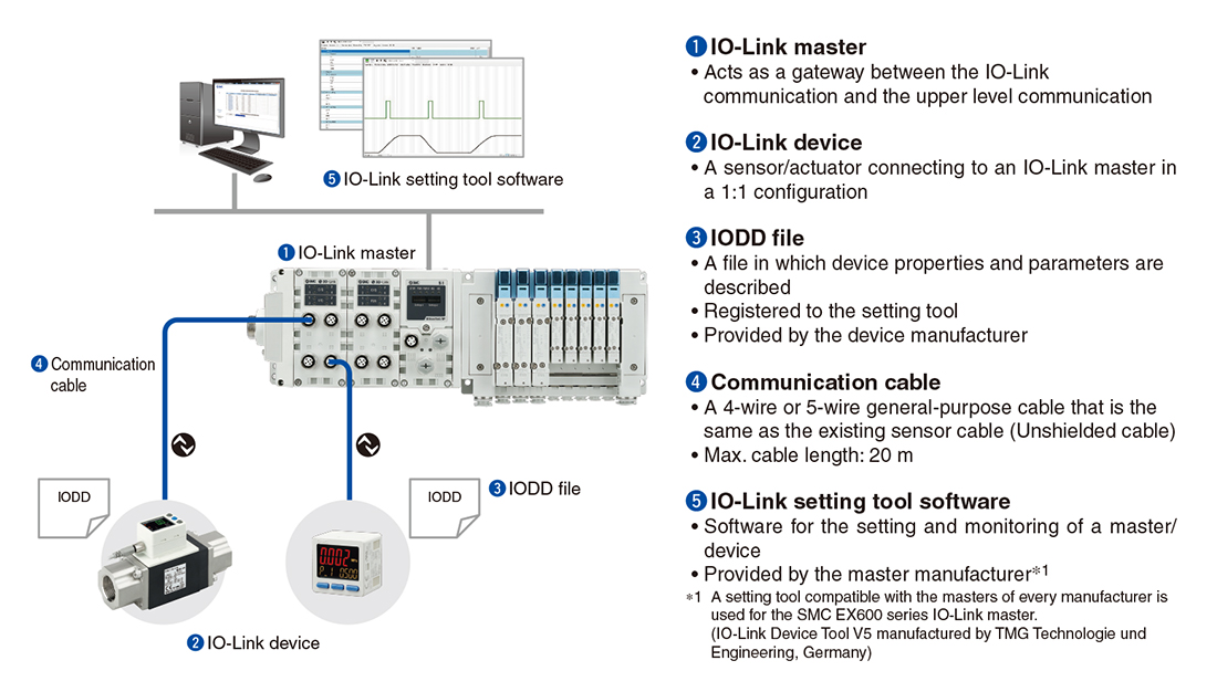
●IO-Link System Configuration
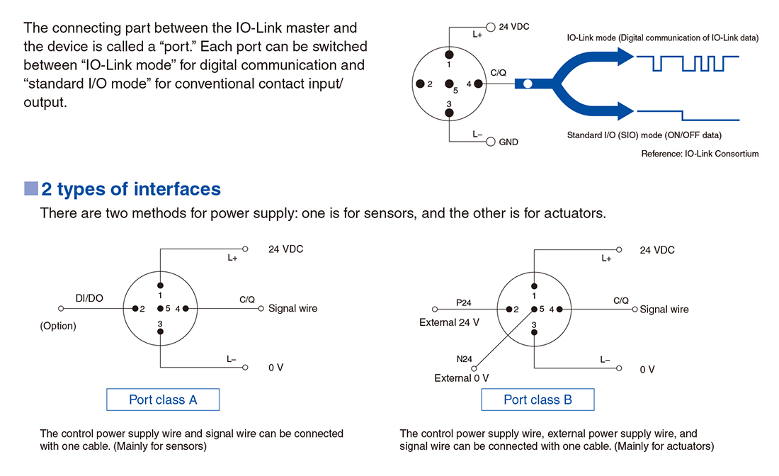
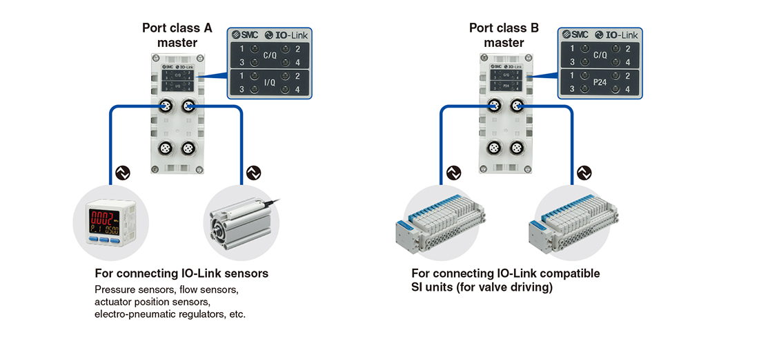
●IO-Link Interface
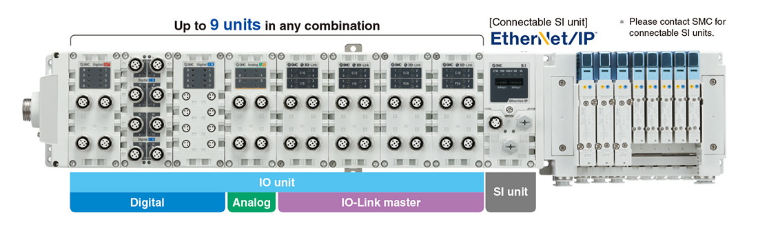
●IO-Link Master Unit
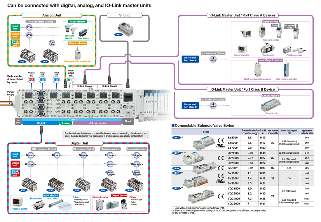
Can be connected with digital, analog, and IO-Link master units
Up to 4 IO-Link master units can be connected. (Total of 16 ports)
* When connecting the EtherNet/IP™ unit
Digital units, analog units, and IO-Link master units can be mixed, and up to 9 units can be connected in any order.
Supports both port class A and port class B
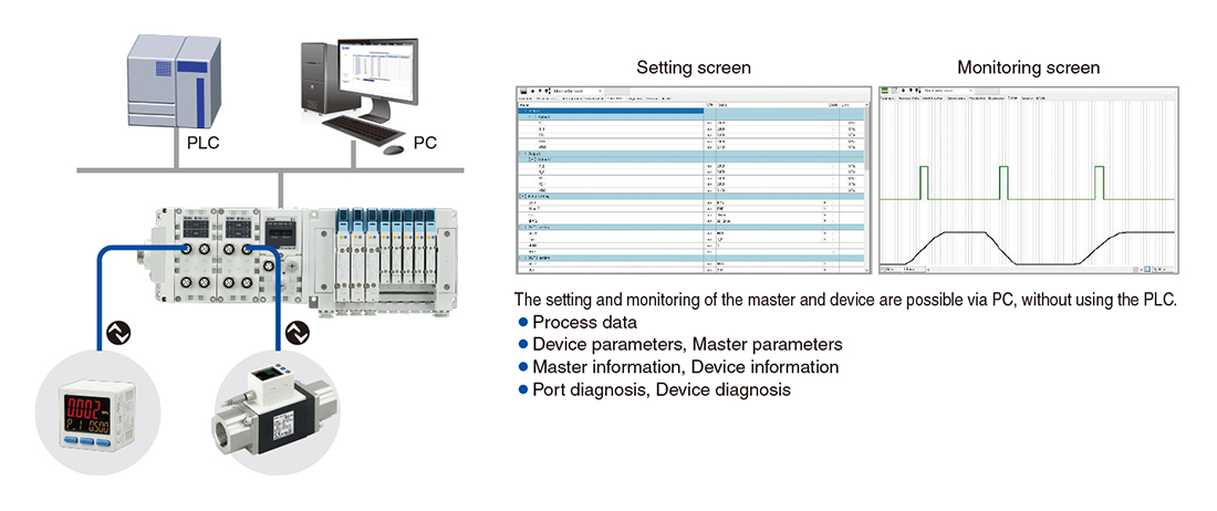
The data can be accessed from via PC (setting tool).
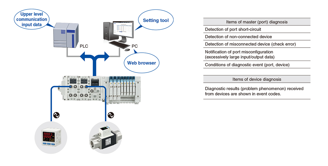
Diagnosis function
Diagnosis on a master and device is possible from the upper level communication.
Master (port) diagnostic information can be obtained via PLC program or PC (web browser).
Device diagnostic information can be obtained via PC (setting tool).
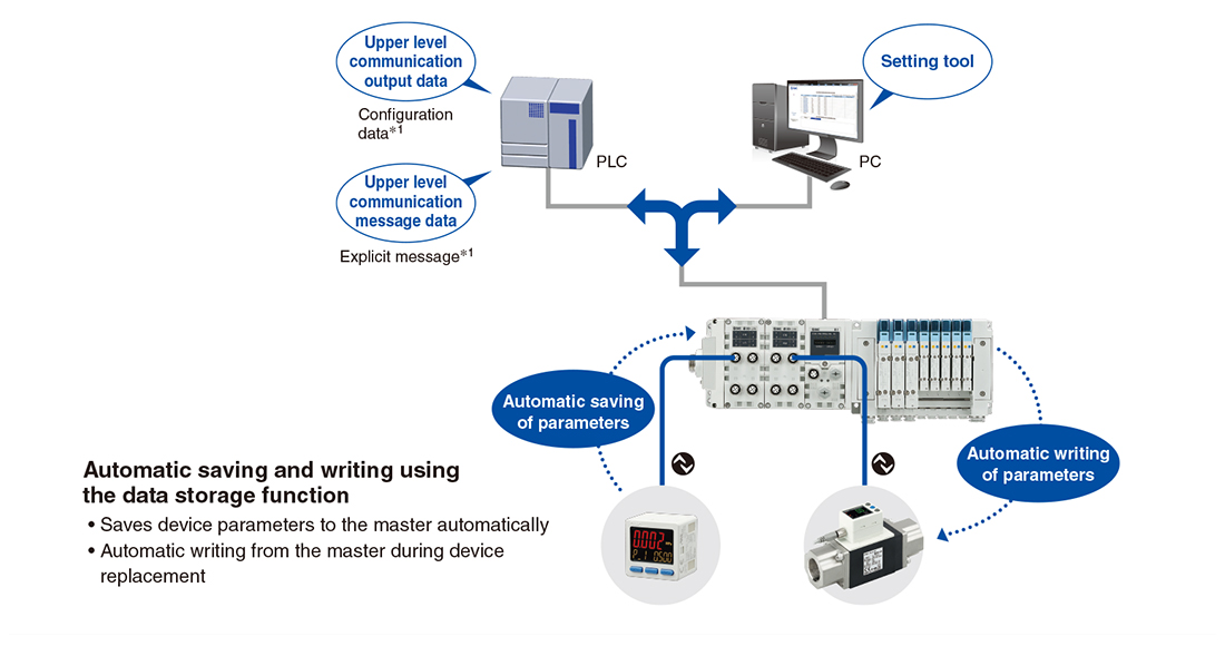
Device parameter setting function, Automatic saving/writing
The parameter setting of devices is possible from the upper level communication.
Parameter setting is possible via PC (setting tool).
It is also possible to use output data or message data via PLC program.*
* For EtherNet/IPTMcommunication
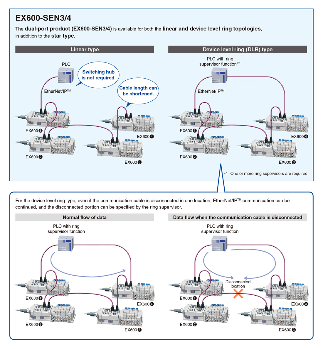
The following functions are available for the dual-port EtherNet/IPTM product (EX600-SEN3/4).
●Added: Compatible topologies (Connection configuration)
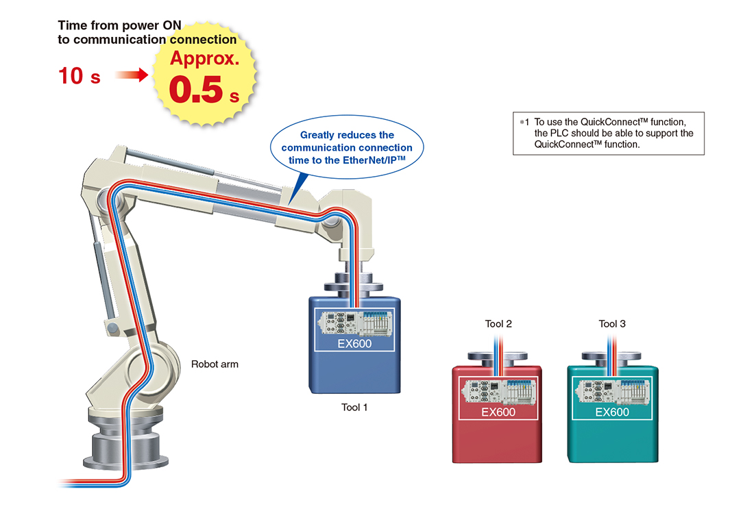
●QuickConnectTM function available
For tool changers, it takes about 10 seconds for communication to be connected in common EtherNet/IPTM products after the power of the device installed on the tool is turned ON.
Since the QuickConnectTM function*1 is available for the EX600-SEN3/4, communication can be connected in about 0.5 seconds.
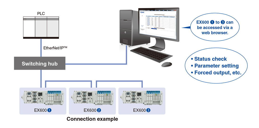
●Built-in web server function
The EX600-SEN3/4 has a built-in web server function, which enables status checks, parameter settings, and forced output of the EX600 using general-purpose web browsers, such as Internet Explorer. Start-up of the system and maintenance can be performed efficiently.
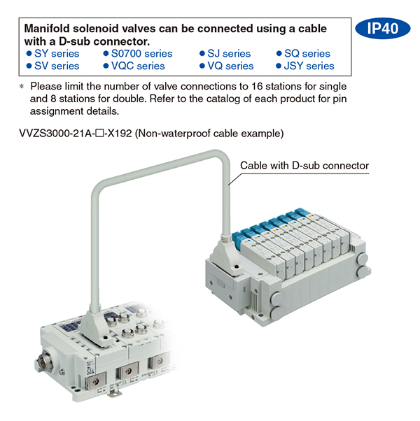
●D-sub connector
These units are capable of connection using a D-sub connector.
There are three types of units: for digital input, output, and input/output.
The digital output unit can be connected with an SMC manifold solenoid valve F kit (D-sub connector).
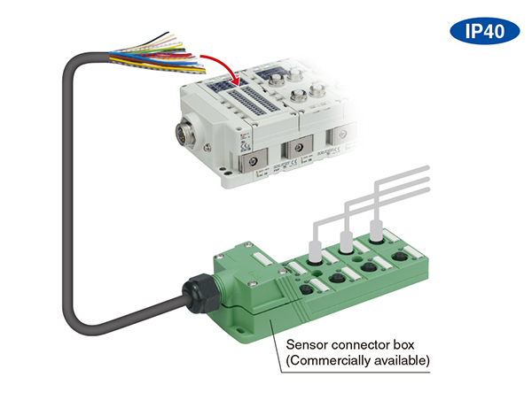
●Spring type terminal block
These terminal block units are compatible with individual wiring configurations.
There are three types of units: for digital input, output, and input/output. Wiring connection to a sensor connector box, etc., can be carried out easily using only a flat head screwdriver.
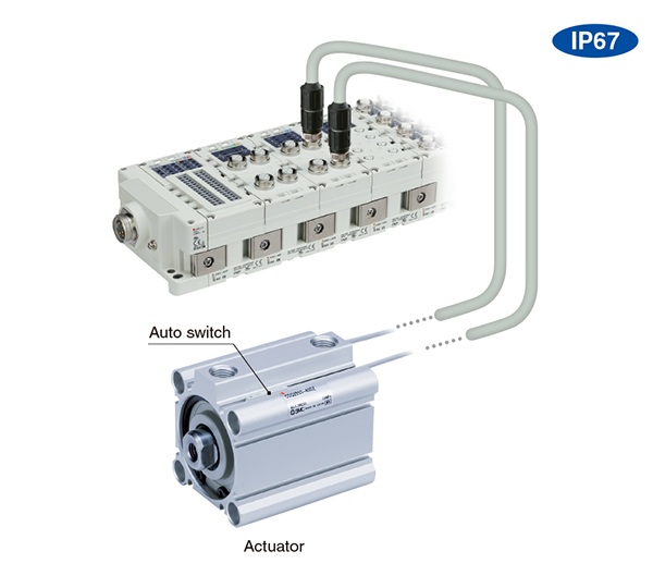
●Digital input unit
This unit is for inputting a digital signal (ON/OFF signal). The signal of a 2-wire/3-wire auto switch attached to the actuator can be acquired to feedback a signal to the PLC.
The control signal of an entire system can be managed by a Fieldbus system.
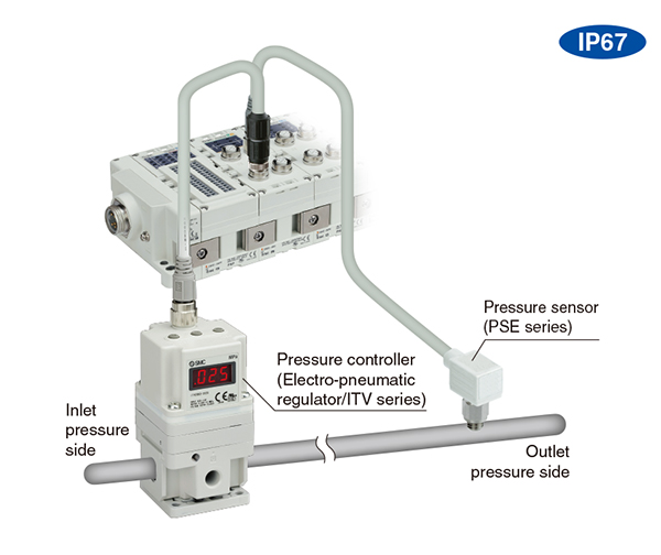
●Analog input/output unit
These units are for inputting or outputting an analog signal (voltage/current). A single unit performs both input and output, allowing feedback control where analog signals are received from a pressure sensor and sent to a pressure controller. Installation space is minimized as well.
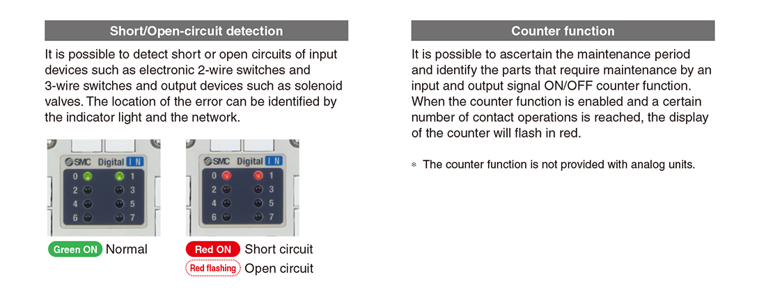
●Self-diagnosis function
The following shows examples of the self-diagnosis function.
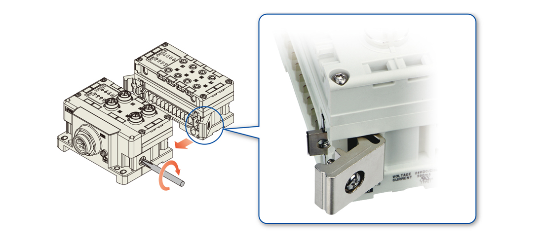
●Individual units can be connected and removed one by one.
A unique clamping method is adopted to prevent screws from falling out. Units can be separated easily by loosening the joint bracket. Up to 9 units can be connected in any order. * Excludes SI units